

Servo Serial Creation
Prepare the Basic Servo for New Electronics[edit | edit source]
- Remove the 4 screws and bottom cover from a basic servo.
- Separate the screws and covers; set aside.
- Remove the gearbox & bearing (top cover), gears, and shafts.
- Set aside, protect from dust.
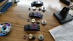
Screws and gearbox removed from Servos. - Pull the PCB out of the servo body.
- Clip the motor leads at the PCB.
- Remove the screw securing the position potentiometer.
- Remove the potentiometer and servo PCB; discard to salvage.
- Use a hard surface to push potentiometer shaft into servo body to break glue and snap it loose.
- Remove any glue remaining in the servo body.
- Useful tools: tweezers, #2 pencil eraser, compressed air.
- Extract the pin from the spline gear (see photos).
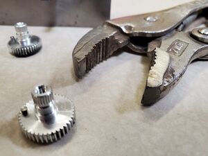
Close up perspective of servo spline gear. - If the top bearing is stuck on the spline gear use the servo bearing wedge set (TL-SBSW) to remove it.
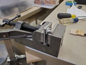
- Clamp the spline gear between the spline gear vise jaws (TL-SGVJF and TL-SGVJB) in a machinist vise, with the 3/16 inch spline gear vise jaw hinge (TL-SGVJH) inserted between the vise jaws at the bottom (see photo).
- The spline gear vise jaw set (TL-SGVJS) comprises TL-SGVJB, TL-SGVJF, and TL-SGVJH.
- Clamp the pin in the end of the "pin-puller" vise-grip jaws (TL-PPVG).
- The clamping force must be sufficient to create opposing flats on the pin.
- The specially-ground flats jaws of the pin-puller are not parallel; they should form a wedge-shaped "head" on the pin.
Pin clamped inside of a "pin-puller" vise grip jaws.
- The specially-ground flats jaws of the pin-puller are not parallel; they should form a wedge-shaped "head" on the pin.
- The clamping force must be sufficient to create opposing flats on the pin.
- Rotate the pin back and forth about its axis by twisting the pin-puller. After the pin has been rotated a cycle or two, begin pulling while continuing to rotate the pin back and forth, and continue to rotate and pull until the pin comes out.
- Deburr the rim of the pin's hole in the spline gear. It must not protrude above the face of the spline gear.


Assemble the Serial Servo[edit | edit source]
- Install the RENC CCA:
- On the RENC CCA, rotate the encoder's hollow shaft so the flat of the d-shaped opening is near and parallel to the PCB edge with the screw cutout corners.
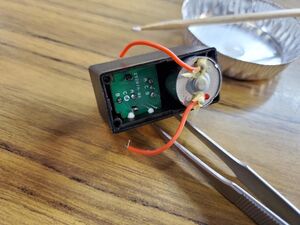
- Insert the RENC CCA into the servo body:
- The encoder side of the PCB goes in first.
- The wires stick up after insertion.
- The PCB screw cutouts align with the screw shafts in the corners of the servo body.
RENC CCA inserted all the way into the servo body with required tool. - The top of the encoder sits flat on the raised boss inside the body that housed the potentiometer.
- The RENC PCB edge with the screw cutouts touches the servo body.
- Option: (omit unless instructed otherwise)
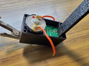
- Apply a small amount of PVA glue (Elmer's white glue) at the edges of the RENC PCB where it meets the sides of the servo body.
- Allow the glue to dry.
Small amount of PVA glue (Elmer's white glue) at the edges of the RENC PCB.
- Install the DSMC CCA:
- Solder the motor leads into the bottom of DSMC CCA.
- The wire from red motor terminal goes to M+ on the DSMC PCB; the other wire goes to M-.
- Use servo motor wiring fixture (TL-SMWF) to hold the CCA for soldering.
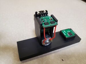
Assembly fixture for DSMC.
- Straighten the RENC wires with tweezers.
- Carefully position the DSMC CCA into the servo body, feeding the RENC wires straight through the A, C, & B pads, and tucking the motor wires between the motor and the RENC CCA, to fit the DSMC PCB into the recess in the bottom edges of the body.
- Gently tug the RENC wires straight with tweezers.
- Solder the RENC wires into the DSMC PCB and trim the leads to the solder joints.
- Solder the motor leads into the bottom of DSMC CCA.
- Insert the D-shaped end of rotary encoder shaft into the encoder through the servo body's spline gear hub.
- The flat of the D goes toward and parallel to the short end of the servo body nearest the hub.
- Ensure the D-shaped end of the shaft mates with the encoder's matching D-shaped hollow.
- When it does, the round part of the shaft drops entirely inside the body.
- Re-assemble the gear train:
- Install bottom gear on the brass bearing in the middle of the gearbox. Insert the long gear shaft through the bottom gear and into the bearing.
- If removed previously, Insert the short gear shaft into the shroud above the motor pinion.
- Install the "hat" gear on the short shaft.
- Rotate the encoder shaft so the flats align with long dimension of servo body.
- Install the spline gear onto its hub
- It's pin hole toward the near end of the servo body and its coupling aligned to mate with encoder shaft.
- Support the RENC CCA so the gear doesn't push it out of position, and ensure the encoder shaft properly engages the spline gear coupling.
- Squeeze the spline gear and PCB toward each other.
- Ensure the spline gear spins freely throughout the full 360 degrees of rotation.
- Install the top gear.
- Ensure the top gear teeth mesh properly with both spline and hat gears.
- May need to push shafts slightly apart to enable this.
- If the spline gear top bearing is NOT inside the gearbox (servo top cover), push the bearing onto the spline gear.
- If needed, use the servo bearing pusher (TL-SBP) to seat the bearing.
- Install the gearbox (servo top cover) onto the servo body, ensuring the spline gear bearing is seated onto the spline gear and the two gear shafts seat into their bearings in the gearbox.
- Ensure the seam between the gearbox and body remains closed when pressure is removed.


Program the Firmware[edit | edit source]
- Open the servo project in the Zilog ZDS II debugger.
- Ensure the servo code is current and compiled.
- Gently secure the servo body upside down in a small vise so the DSMC CCA is accessible from the top, making sure the gearbox doesn't fall from the bottom.
- Ensure the debugger is stopped.
- A second pair of hands may be helpful for this section.
- Engage the programming cable pogo pins into the PCB DBG pads (black to GND).
- These pins must remain manually engaged from now until programming is complete.
- Connect the actuator controller cable to the servo, make sure the brown wire goes to GND.
- Note: This is only AFTER the programming cable is connected.
- Click the [Download code] icon in ZDS II.
- You may need to also click "OK" if hardware version B warning appears.
- When programming is complete, click the ZDS II debugger's [Stop] icon.
- Disconnect the programming cable.
- Disconnect the servo cable.
- Unclamp the servo and turn it gearbox-side up in the vise, making sure the exposed electronics don't touch the vise.
- Re-connect the servo cable, making sure the brown wire goes to GND.
- Note: Disconnecting and reconnecting this cable reboots the servo.
- Make sure both Ucom and Dcom are connected.
- Open Serial Port Terminal and test the servo operation:
- Issue 'z' commands until the firmware version appears in response.
- Up to three tries may be required, because buffers are left in indeterminate states when cables are disconnected.
- Mark a dot on the face of the spline to make its rotational position obvious.
- Issue 'g96' and observe one full counter-clockwise rotation of the spline, as viewed from above the servo.
- Issue 'g-96' and observe one full turn clockwise.
- Issue 'g1' and 'g-1' several times and observe small incremental motions in the appropriate direction.
- Issue 'z' commands until the firmware version appears in response.
- Disconnect servo cable.
- Machine bottom cover.
- Check the DSMC bottom cover to make modify this part.
- Install the machined bottom cover.
- Install and tighten the original 4 screws that hold the servo together, just tight enough to completely close the seams.