Actuator Bellows Sealed Valve Creation
Appearance


Introduction
This actuator operates a bellows-sealed valve. Figure 1 shows the actuator components. The frame bearing at the bottom of the figure attaches to the valve at a later stage, when the actuator is mated to the valve. Although it is part of the actuator, it is not used in this procedure.
Instructions
The order of these steps is not critical. Either the coupling or the frame may be installed or removed with the other already in place.
Assemble the coupling to the servo
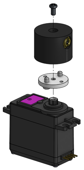
Refer to Figure 2.
- Place the servo on the work surface with the drive spline facing up.
- Press the coupling driver onto the servo spline.
- Place the actuator coupling onto the servo wheel coupling driver. The screws in the driver fit into cavities in the bottom of the coupling. (These screws do not need to be turned.)
- Important: Insert a 1/16" hex key into the set screw in the side of the coupling. The hex key serves as a lever in the next step.
- Secure the coupling and driver to the servo spline with the M3 screw, using a #2 Phillips screwdriver.
- Tighten this screw very securely. Use the hex key to prevent the coupling from rotating while the screw is tightened.
- Note: Many M3 screws accept a #1 Phillips screwdriver, but this one requires a #2.
Assemble the frame to the servo
Refer to Figure 3.
- Place the frame onto the work surface.
- Place the actuator with coupling onto the frame with the mounting holes aligned.
- Secure the servo to the frame with four 6-32 x 1/4 screws, using a #2 Phillips screwdriver.